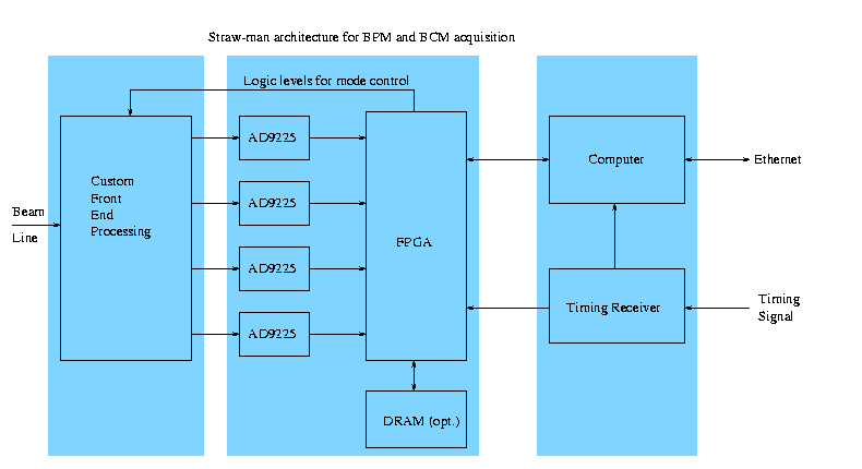
Straw-man architecture for BPM and BCM acquisition
Historical interest only: unchanged since February 2000
While I provide a list of plausible chips below (if the boards
were to be constructed today), the point is to generate an interface
that can last even as chips come and go. The test for this (and
any other) architecture is, can one plan to rebuild any given board
at any time in the next 25 years, with whatever technology is on-hand
at the time? Part of this question is, are the interfaces fully
documented, and relatively simple, so we can expect that implementations
will be bug-free?
(eps copy)
Each blue rectangle represents a circuit board, more on the construction
below. The two rectangles on the left are repeated a few times per
computer, mostly determined by how cables conveniently run.
6 copies are appropriate for one MEBT raft.
Less than 4 doesn't sound cost-effective. More than 10 would probably
swamp the backplane, computer, and network.
Specialized front ends:
- Log-amp based BPM
- Mixer based BPM/Phase detector
- Direct (1.2 MHz) BPM
- FCT BCM with diplexer (handle both 1.2 MHz and 402.5 MHz)
- ADC:
- AD9225, 280 mW, 25 MS/s, $20.00. Note that the average power
dissipation for this and every other chip will be about 1/16 of
the given number, since we can disable almost the whole crate
between pulses.
- FPGA:
- XC2S100-5PQ208C, 208-pin LQFP, just announced, mythical $10.
or XCS30-3PC208C, 208-pin LQFP, real $45.35
- DRAM:
- 2 or 4 times 4Mx16 DRAM.
- MT4LC4M16R6 EDO-RAM, 20-25ns write cycle.
- MT48LC4M16A2TG-8E SDRAM, 10ns write cycle, $26.66 from Arrow.
- MT48LC4M16A2TG-8EIT, $34.68 from Arrow.
- MT4LC4M16TG5 for $23.16 from Arrow.
Provides snapshot memory for full 4 X 19 MS/s for multiple 1 ms pulses.
Page mode write cycles need to be interrupted every 512-1024 cycles
to change pages.
- Computer:
- EP7211 (32-bit 66 MIPS for $26.23) with 16 MB RAM, 4 MB Flash,
Ethernet.
- Timing Receiver:
- FPGA based, with 76 MHz VCO locked to incoming signal.
- Backplane:
- JTAG chain to load each FPGA from the computer. 8- or 16-bit
wide communication channel to the computer. 76 MHz, 1.19 MHz and
at least one event trigger from the timing receiver.
Because of the JTAG connection, the backplane and its connection to each
FPGA is fully in-place testable. However, an FPGA with a broken JTAG port
(or a missing board) keeps the rest of the crate from being programmed.
JTAG files to support each specialized front end are kept on the 'net.
The Flash memory on the computer is only enough to boot.
Normally, only heavily averaged data is transmitted from the FPGA to
the computer, after each beam pulse. A snapshot of raw ADC values
sticks around in RAM, so a history can be regurgitated on demand.
The computer does the complex manipulations like linearization, before
passing output to the Ethernet port.
The computer does not necessarily run EPICS. If not, it would spit
out regular UDP packets containing the per-pulse summary information
to an EPICS computer, which would then gateway that information to
the rest of the net. The EPICS computer would also necessarily relay
some tcp connections for more intimate debugging, and possibly the
raw waveform dump function mentioned before. This mode has the advantage
that the CPU horsepower needs are lower, and the net bandwidth needs
are lower. I haven't seen embeddable 100 MB/s Ethernet subsystems,
while 10 MB/s Ethernet is widely available in single-chip form.
The ADC/FPGA board is intended to be common across the specialized
front ends, but gets mated and tested with a front end before insertion
in a crate. Both the ADC/FPGA and Front End boards should have a
form factor about 10cm square, but a little bigger is OK. 10x20 cm
is more than big enough for the computer.
I imagine a crate holding all these cards tucked in close to the
beamline in the MEBT. I am told this thing needs to be waterproof,
so the cableway needs a cover with a foam rubber gasket on the bottom
where the cables come out (see the next paragraph).
Add 1cm on the bottom for LO and Calibration splitters, and 4 cm
cable space enclosed by the cover, and the total box is about
11x12x25 cm. Note that the power consumption of all this probably
tops out at about 1 Watt per board, so conduction cooling should
be plenty. No fans! Board count for 1 MEBT raft:
- 4 x BPM front end
- 1 x FCT BCM front end
- 1 x general purpose spare front end
- 6 x ADC/FPGA
- 1 x computer
Besides the dozen or so .141 hardline
connections to the beamline, there are the following connections
to the control racks:
- power (DC unreg?)
- Ethernet
- Timing
- LO (402.5, 805, 1207.5 MHz)
- Calibration
- remote reset
I'd like to see all this bundled up, maybe with spiral wrap.
It looks like two .141 hardline, at least one CAT5 cable, and
a (low voltage, thick wire) power cable.
I have not made provision here for a remote 'scope connection (multiplexed)
to the Front End signals. At JLab, such a thing is called an "Analog
Monitoring System."
I would like to see some status lights, like
- DC Power OK
- Timing signal OK
- Beam trigger/acq
- Ethernet RX
- Ethernet TX
- Software heartbeat
- Remote reset
I don't have a good plan to make lights that are visible from a distance,
protected from water, don't have a lot of hand wiring, and are compatible
with quick-change cards in a backplane.
Larry Doolittle
January 19, 2000