original compressed PostScript form
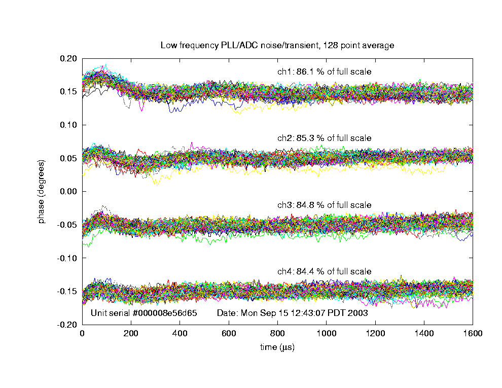
Here is one measure of the phase stability of the LLRF system. Measuring this is part of the qualification process for one of our "g2" LLRF boards.
original compressed PostScript form
With an input trigger of 20 Hz, and a 70 microsecond warm-up for the ADCs, we measure 1.6 ms of data on a single channel for 4 seconds, about 80 waveforms. Waveform averaging is set to 128, meaning each data point combines 128 I or Q samples from the ADS808 12-bit converter, covering 128 * 0.05 = 6.4 microseconds. Multiplying this by 256 points in each waveform gives the overall horizontal span of 1638.4 microseconds.
The 50 MHz input from the bench synthesizer is fed to both the channel under test and the PLL input. Cable lengths are adjusted so one of I or Q is near the zero crossing, and thus (when divided by the other and converted to degrees) represents phase of the input. The measurement is repeated for each of the 4 input ADC channels.
Several effects can be noted in the result:
(The 0.1 degree offsets between the four input channels are imposed artificially to make the display legible.)
Larry Doolittle
October 27, 2003