Actual slide text
Quotes, also shown on slides
Notes to myself, will be memorized, paraphrased, and spoken
Images are not to scale
17 slides, 11 quotes, 10 minutes!

"Problems worthy of attack
show their worth by hitting back."
- Piet Hein (1905-1996), Danish inventor, mathematician, poet, philosopher

I tell people that the LLRF systems we build are a combination op-amp and digital storage 'scope. In this talk I will explain the basic functionality that's required of an LLRF system, and how it is implemented in hardware and software. This is important to accelerator engineering as a whole, because the LLRF interacts with so much else in an accelerator. Global choices in the architecture and infrastructure of an accelerator have huge consequences in the cost and performance of the LLRF.

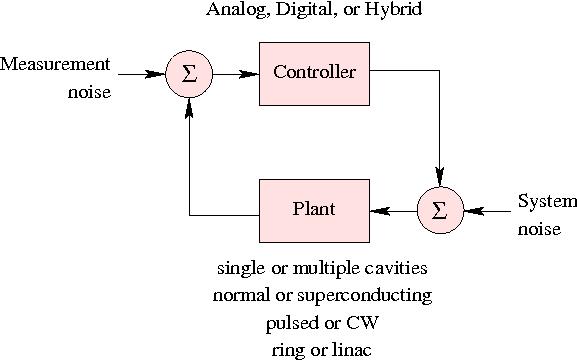
Classic textbook feedback system diagram. Some things not well absorbed by the model are:
connection between plant characteristics and controls choice
Much of what I say here is irrelevant to the shortest pulse machines (e.g., SLAC-style linacs) that only permit pulse-to-pulse feedback. Those machines have additional design flexibility, since latency doesn't matter.
Gain = K_P + K_I/s
"A complex system that works is invariably found to have evolved from
a simple system that worked."
- John Gall, U.S. author
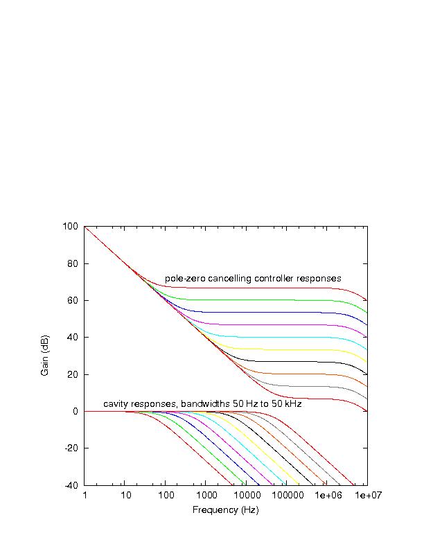
cavity bandwidths can vary from 50 Hz to 1 MHz
feedback is useful for cavity bandwidths up to 50 kHz
dominant limitation on feedback gain is group delay around controller, especially cables and waveguides. 1 microsecond group delay limits GBW to 100 kHz.

Gain = K_P/(1+s tau) + K_I/s
broadband (up to 5 MHz) gain of 70 dB is not practical, too much noise sent to Klystron. Here is the consequence of limiting noise bandwidth, and maintaining similar phase margin.
Physics/perturbations to be addressed
Pulsed machines can use pulse-pulse feedback, a.k.a. feedforward or adaptive feedback
"The cheapest, fastest and most reliable components of a computer system
are those that aren't there."
- Gordon Bell (1934-), U.S. computer engineer
"Embrace simplicity.
Put others first.
Desire little."
見素抱樸少私寡欲
- Laozi (4th century BC?), Chinese philosopher


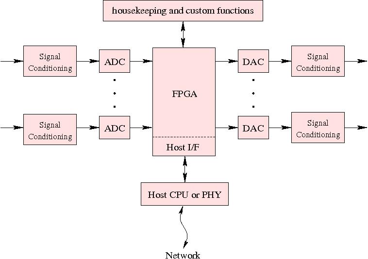
Familiar block diagram: all accelerator front-end measurement and control equipment should fit this general framework.
include "signal conditioning" on input and output
Some add DSP as a separate block, but FPGAs are big and fast enough to absorb that functionality
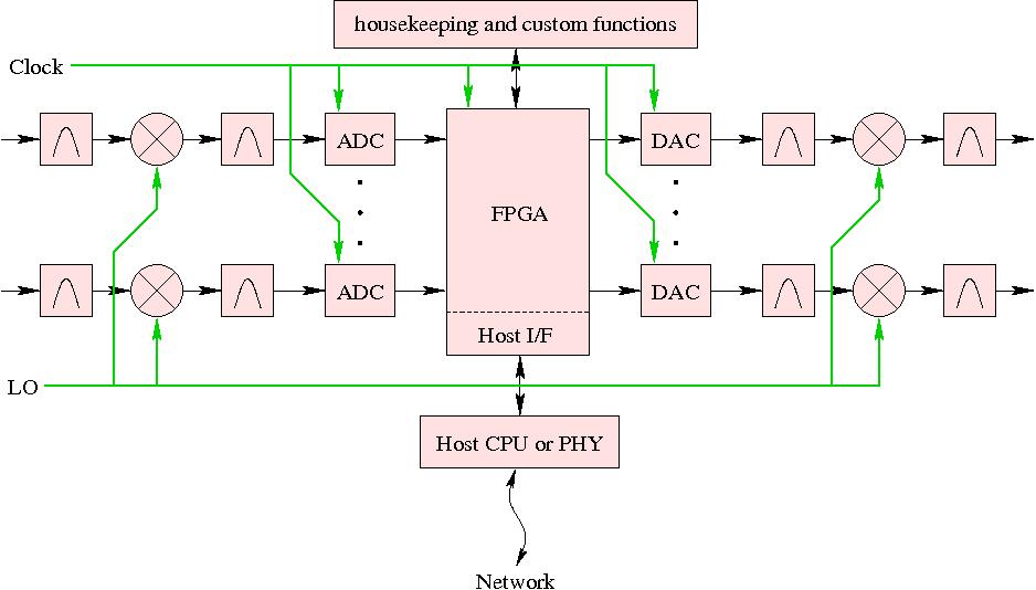
ADC will never compete with a mixer for phase noise / additive jitter, essential for RF above ~100 MHz
Typical downconversion is to an IF in the 30 to 100 MHz range, placed in the second or third Nyquist zone of the ADC.
DAC chain is less critical than ADC, because of its placement after the feedback gain.
Communication grade ADCs are now available and affordable for large scale use in the 12- to 14-bit range, 65 to 170 MS/s. Latency seems stalled in the 30 to 80 ns range.
Hardware concerns:
| Computer | FPGA | |
| Programmable digital logic device | Yes | Yes |
| Major suppliers | uncountable | 2 |
| Glue-less hookup to most DAQ hardware | - | Yes |
| Guaranteed low-latency processing | - | Yes |
| Good programming languages | Yes | - |
| Good programming requires thought and experience | Yes | Yes |

One FPGA chip has thousands, or even hundreds of thousands, of these basic repeat units, that can clock upwards of 100 MHz. The programmable routing between them is a big deal. But wait, there's more! The chipmakers throw in a bunch of multipliers and RAM for free! Cost per cell can be less than a U.S. cent, or a few tenths of an Indian Rupee. The original SNS controller fit in 3400 cells. I consider a 10- to 20-thousand cell FPGA perfectly fine for a single cavity controller.
Languages to describe (parallel, concurrent) hardware are decades behind those used to program von Neumann architectures. VHDL and Verilog are both pretty bad, actually.
"VHDL was written by a bunch of software guys who knew nothing about
designing hardware. We beat on it until you could do hardware with it.
Verilog was written by a bunch of hardware guys who knew nothing about
designing software. We beat on it until you could do software with it.
Neither does the job they were originally intended to do, but they work."
- David Bishop, Engineer, posting in comp.arch.fpga
"When someone says 'I want a programming language in which I need only say
what I wish done,' give him a lollipop."
- Alan Perlis (1922-1990), U.S. computer scientist

"Be patient, man. I'm trying to be linear."
- A.L.F.,
fictional TV alien, 1986-1990

Still have short uncontrolled cables, only way to eliminate that is with interferometry.
This is the most important slide! fundamentally something digital LLRF can do, but analog can't

Basic idea is the same as an op-amp. Close a feedback loop with lots of low frequency gain. Big difference is that it operates on complex numbers, thus the gain includes a rotation angle. One job of upper level software is to adjust that rotation angle to provide correct negative feedback.
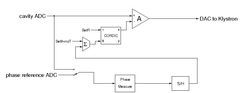
While there is an option of taking the phase reference signal from a separate ADC (and mixer and filter), in a pulsed machine it is trivial to take it from the same ADC as the cavity, just at a different time. Hardware support as shown on previous slide, phase calibration pulse is offset in time from beam pulse.
A CW machine can also passively combine a calibration signal with the cavity probe, but that cal signal (diagnostics folk call it a pilot tone) has to be offset in frequency, not time. That case requires a little extra (digital) work to pull sideband modulation out of cavity ADC signal. Those sidebands need to be in-band for data acquisition chain, but out-of-band for the cavity. It will be suppressed (adaptive feedback) at the input of the main digital feedback amplifier.
Amplitudes can be cross-calibrated in a similar way, but there is no intrinsically correct amplitude source available, the way there is for phase. Simply want an amplitude reference stable enough to hold station between beam energy measurements.

This shows a little more detail of how the functionality maps to hardware.
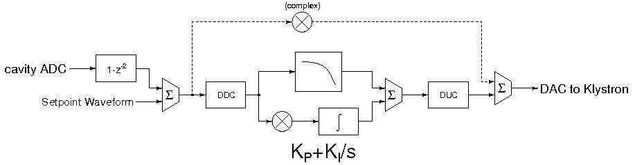

Conversion between IQ and not takes a couple cycles, adding to loop group delay. But can be mostly combined with other functions, like phase rotation. Estimate penalty 4 cycles at 65 MS/s, or 60 ns.
This version includes double-data-rate on the output DAC, and does not show fancier feedback possibilities: 1/sqrt(s), and State Variable Filtering (which would be nice to use for microphonic tuner control).
Modern FPGAs have pushed throughput way up, but without as much concern for latency. The claim of "400 MHz" on some FPGAs only applies if you have 4 cycles of pipeline per multiplier. Makes the year 2000 technology 25ns multiply/add look not so bad (well, that was 12-bit, contrasting it with today's 16-bit).
This version shown without the extra complex multiplier that can short-circuit the demodulation/modulation step, providing a direct feedback path from input to output in about 8 cycles total.
"What's the difference between hardware and software?
Hardware keeps getting cheaper, faster, and smaller."
- Rick Cochran, Cornell network administrator

stage 0: physics modelling, with theoretical control system
stage 1: FPGA components with artificial test bench
stage 2: virtual world; hardware/software cosimulation, with physics
plus: use FPGA as a test bench for global controls!

Additional mandatory features:
"It is easier to move a problem around than it is to solve it."
- Ross Callon, U.S. network engineer
Written in 1996 as RFC-1925; as of 2004, Ross is a Juniper Networks Distinguished Engineer. I leave out the (for example, by moving the problem to a different part of the overall network architecture) part.
Diagram represents not only the physical relationship between accelerator subsystems, but the communities that design, build, and commission them.
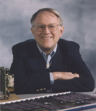
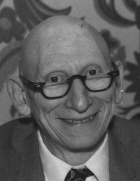
Photo of LBNL/SNS Interim
2001
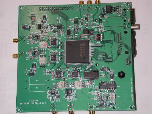
Photo of LLRF4
2006

Software
"Perfection is achieved, not when there is nothing more to add, but when
there is nothing left to take away."
- Antoine de Saint-Exupéry (1900-1944), French writer and aviator

Il semble que la perfection soit atteinte non quand il n'y a plus rien à ajouter, mais quand il n'y a plus rien à retrancher.
Thank you for your attention!

thanks in Hindi: DHAN-YA-VAD
Acknowledgments:
people who have contributed in one way or another to the work that led up to this talk.
Image credits: Wikipedia, Wiley Miller
This talk is online at http://recycle.lbl.gov/apac2007/
ready for Babelfishing
"I have only made this letter rather long because I have not had time
to make it shorter."
- Blaise Pascal
(1623-1662), French mathematician and philosopher

Je n'ai fait celle-ci plus longue que parceque je n'ai pas eu le loisir de la faire plus courte.