LBNL LLRF Expansion Board
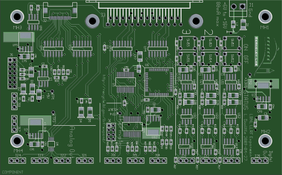
(actual size 5.0 x 3.1 inches = 127 x 79 mm)
Top-level "specs":
- 3 Photodiode Bias ports: +5V out, current monitor to 10 mA full scale (and trip)
- 3 Thermistor ports
- 2 Optical atten control ports: few mA, few V
- 2 VCXO control ports: few mA, few V
- control and readout via digital I/O on existing LLRF4 board
Translated to something more real:
- 3 x 10mA 5V regulator with enable: 3 x LP2989
- 3 x high-side current sense: 3 x MAX4172
- 3 x over-current comparator: 3 x TLV7211
- 3 x 14-bit 200 kSample/s ADC: TLC3548I (bias current monitor)
- set/trip/reset remote/local digital logic: XC9536XL
- 3 x 24-bit 60 Sample/s ADC: AD7794 (50 kOhm thermistor bridge)
- 4 x 14-bit 500 kSample/s DAC: AD5644 (VCXO and Optical atten, unbuffered 0 to 2.5V)
- SPI-like expansion ports for LLRF4 FPGA (code not written, except for AD5644)
- power input nominally +12V, but LP2989 will work with +6V to +16V
Design Tools
The schematic is done in xcircuit,
and the board layout is done in PCB.
Both are Free Software.
They may or may not be available or useful on Microsoft-based computers.
This board design was done on
Debian 5.0 (Lenny),
a stable Linux distribution.
Specifically, this was Lenny's stock xcircuit (3.6.135), and pcb was
updated to pcb-20080601 to get the photo-realistic board preview feature.
Packets for Download
Larry Doolittle, LBNL
April 27, 2009